Selection Guide for SolidMatrix® and AirMatrix® Fuses
Introduction
This Guide provides technical information for how to select AEM SolidMatrix® and AirMatrix® SMD fuses. Detailed tests are required to validate your selection because various extraneous factors exist with different circuits.
Parameters
Consider the following parameters when choosing a proper AEM SolidMatrix® and AirMatrix® fuse:
1. Maximum Steady State operating current
2. Maximum operating temperature
3. Waveform of maximum transient pulse current
4. Pulse cycle
5. Overload current and corresponding breaking time
6. Possible maximum fault current in applications
7. Maximum operating voltage
8. Dimension
9. Compliance standard
Definition of parameters
1. Operating temperature and temperature de-rating
The operating temperature of AEM SolidMatrix® and AirMatrix® fuses is between -55°C and +125°C. "All electrical parameters, such as the clear time characteristics are obtained under room temperature" (+25°C).The temperature derating curve should be referred when the operating ambient temperatures is above 25°C. Figure 1 shows the temperature derating curve of our fuse.
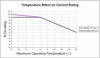
Fig.1 Temperature derating curve
2. Operating voltage and rated voltage
The systems maximum operating voltage should not exceed the fuses rated voltage. In addition the voltage rating must be greater then the maximum open circuit voltage to preclude arcing.
3. Interrupting Rating
Interrupting rating refers to the maximum current that can safely be interrupted by a fuse under rated voltage. As a safety parameter, the interrupting current of a fuse must be equal to or greater than the maximum fault current in a circuit. In this way, the fuse may break safely without causing any hazards, such as fire, arcing, or explosion.
4. Operating current and rated current,In
The maximum current of a circuit in steady state is called the operating current. Refer to the data sheets for the rated current of AEM SolidMatrix® and AirMatrix® fuses. According to the international standard, fuses must work without blowing under rated current for at least 4 hours (ambient temperature: +25°C). To ensure long-term steady operation, a fuse's operating current should be less than 75% of its rated current.
5. I2t value and pulse derating
A large pulse current may occur when the power is on or off because most circuits have energy storage components, like capacitors or inductors. Transient pulse may also result from other components or external factors like electromagnetic reaction. In most cases, customers expect that fuses can withstand multiple pulse shocks without blowing.
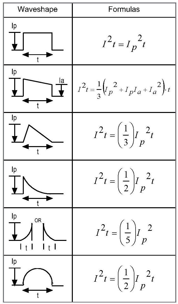
Table 1 below lists the formulas for common pulse waveforms. The I2t value of pulse current can be calculated from the integration of pulse current wave data.
Tab. 1 Formula for common pulse waveforms (I2t value)
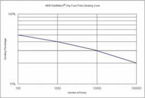
When a pulse flows through a fuse, heat may be produced. However, although the energy from one pulse may not be strong enough to blow the fuse, multiple shocks may be. To enable the fuse to resist multiple pulse currents, its I2t specification should be calculated with the pulse derating factor shown in Table 2. When a pulse occurs, corresponding temperature derating is required if the fuse is placed under ambient temperature that is higher than room temperature (+25°C).
Tab. 2 Pulse derating percentage of AEM SolidMatrix® and AirMatrix® fuse
The ratio of Ir2t value of pulse current to If2t of fuses | Number of pulses to withstand |
Ir2t<= 20% If2t | 100,000 |
Ir2t<= 30% If2t | 10,000 |
Ir2t<= 40% If2t | 1,000 |
Selection process
For the following parameters, item 1 and 2 are steady state, and item 3 - item 6 are transient state.
Steady State parameters
1. Rated current(In)of a fuse >= operating current (I)/75%.¨2. Based on the operating temperature, ensure the temperature derating factor (K) meets the formula for calculatingfuse current required by steady parameters: In>=I/75%/K
Transient State parameters
3. Calculating the I2t value of pulse current: refer to the formulas for common pulse waveforms in Table 1. For complex or non-typical waveforms, the value can be obtained with the integration of data from a digital oscilloscope; Or with a simplified calculation method, i.e., calculating with a similar typical pulse waveform that can entirely cover the waveform. 4. Pulse derating: find the pulse derating factor based on the required number of pulses to withstand. 5. If the ambient temperature is greater than the room temperature when a pulse occurs, corresponding temperature derating is required. 6. Confirm the minimum current of the fuse to withstand the number of pulses.
Safety Standards or circuit protection regulation
7. Make sure the fuse complies with safety standards and regulation or circuit protection requirements, e.g. the maximum I2t withstanding value of the protected IC, the maximum current and time that keep the cable from overheating, and so on.
Choosing the fuse meeting your design code
In the results from the above-mentioned Step 2 and 6, the larger rated current of the fuse determines the lower limit of the design window, while Step 7 decides the upper limit. The specification of the fuses to be selected should fall within this design window.
Test verification
The specifications calculated from the previous steps have to be verified and tested with actual circuits, especially in an environment similar to actual operation. Full life tests shall be conducted according to the required number of pulses to withstand.
Example
The following example describes the previous selection process.
Circuit parameters:
1. Maximum steady operating current: I=0.6A
2. Operating temperature: +65°C
3. Waveform of maximum transient pulse current (Sine wave)maximum current Ip =45.5A, pulse width t=120Sec
4. Required number of pulses to withstand: 100,000
5. Overload current and corresponding breaking time: I=10A, 60Sec
6. Possible maximum fault current in application: 50A
7. Maximum operating voltage: 12V
8. Dimension: 1206
9. Compliance standard: UL Recognized
Calculation of steady state parameters:
The minimum rated current of the fuse to meet the requirements of steady parameters is In >= I/0.75 (current derating factor)/K (temperature derating factor)= 0.6/75%/90% =0.89A. In this way, the fuse with its rated current larger than or equal to 1A is acceptable.
Calculation of transient parameters:
I2t value:
Refer to the formula in Table 1 to calculate the I2t value of pulse current. The impact of ambient temperature to pulse withstanding capability should be considered at the same time.
I2t value of pulse current:
Ip2t =0.5x(45.52A)2x120µSec= 0.1243A2Sec
This application requires the fuse to withstand 100,000 pulses under +65°C, and thus pulse and temperature derating should be considered concurrently.
If2t >= Ip2t /P(Pulse derating) /K(Temperature derating) = 0.1243/20%/90%=0.69A2Sec
Comparing the I2t vs t curve in AEM's catalog, the specification of the fuse (If2t>0.69A2Sec; t=120µSec) is not less than 3.5A If2t value. Therefore, F1206HI series fuses with the rated current larger than or equal to 3.5A are acceptable.
Protection performance:
The fuse should blow within 60s when the current is 10A. AEM's F1206HI series feature a clear time of less than 60s when the current is twice overloaded (200%). Therefore a fuse with rated current less than 5A may be selected.
Conclusion:
In conclusion, the F1206HI series from 3.5A to 5A may satisfy all product specifications as required above.Considering that the fluctuation of parameters of other components in the circuit may cause the pulse current to fluctuate, a reserved allowance of 30% is recommended to prevent nuisance opening under extreme conditions.
AEM Components (Suzhou) Co., Ltd. AEM and AEM Logo are trade marks. Specifications and descriptions in this literature are as accurate as known at the time of printing, but are subject to change without notice. For the most updated information, please consult the factory. AEM reserves the right to make changes without notification to Buyer to materials or processing that do not affect compliance with any applicable specifications. Users should independently evaluate the suitability of each product for their application. AEM makes no warranties as to the accuracy or completeness of the information, and disclaims any liability regarding its use. AEM's only obligations are those in the Company's Standard Terms and Conditions of Sale for this product, and in no case will AEM be liable for any incidental, indirect, or consequential damages arising from the sale, resale, use or misuse of the product. Copyright© 2010 AEM Components (Suzhou) Co., Ltd.